In Glendale, where the subsurface can shift from dense caliche to loose basin fill within a few hundred feet, guessing the stratigraphy is a costly gamble. We see it often on sites near the New River or along the Loop 101 corridor: contractors hit an unexpected cemented layer that delays drilling for days. Seismic tomography cuts through that uncertainty. The method generates a continuous velocity model of the ground, revealing transitions between stiff conglomerate, compressible alluvium, and weathered granite bedrock. For geotechnical engineers, this means placing a footing on a known bearing layer, not an assumed one. The data also feeds directly into slope stability analyses when the project involves cut-and-fill on the terraces overlooking the Agua Fria River. Our team processes the shot gathers on site, delivering preliminary cross-sections within 24 hours so the earthwork contractor can adjust the excavation plan before the next shift starts.
A velocity cross-section from seismic tomography replaces six to ten exploratory borings when the goal is mapping bedrock depth and lateral continuity.
Our approach and scope
Local considerations
The most common mistake we correct on Glendale job sites is relying on a single boring to characterize a 2-acre parcel. Basin-fill stratigraphy can pinch out over short distances, and a boring that shows 12 feet of sandy silt may miss a buried channel filled with cobbles just 60 feet away. When the excavator hits that channel, the trench box spec becomes invalid and production stops. Seismic tomography eliminates that blind spot. A single 230-foot refraction line images lateral changes in stiffness that no drill rig can capture between boreholes. On one industrial lot near the Glendale Municipal Airport, the tomography data revealed an abandoned concrete culvert buried under eight feet of fill, completely invisible to the boring program. The contractor adjusted the footing layout and saved two weeks of rework. The cost of the survey was less than the change-order delay alone.
Reference standards
ASTM D5777-18: Standard Guide for Using the Seismic Refraction Method for Subsurface Investigation, ASCE/SEI 7-22: Minimum Design Loads and Associated Criteria for Buildings and Other Structures (seismic site class determination), IBC 2021 Section 1613: Earthquake Loads – site classification per shear wave velocity, ASTM D7128-18: Standard Guide for Using the Seismic-Reflection Method for Shallow Subsurface Investigation
Related services
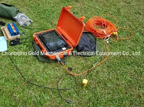
P-wave Refraction Tomography
Standard 2D profiling for mapping bedrock depth, rippability, and lateral velocity changes. Ideal for pre-grading investigations on parcels from 0.5 to 5 acres. Delivers layered interpretation with IBC site class recommendation.
Shallow Reflection Profiling
High-resolution reflection surveys for detecting voids, buried structures, and thin low-velocity zones below slabs or pavements. Uses common-midpoint stacking and migration to resolve features as shallow as 5 feet.
Cross-hole Tomography
Borehole-to-borehole velocity imaging for projects where surface access is limited. Accurate to 1-foot resolution between drill holes. Used for verifying grout curtain continuity and compacted fill stiffness.
Vs30 and Site Classification
Refraction-to-shear-wave conversion for estimating Vs30 per IBC procedures. Combined with MASW when a direct shear-wave velocity profile is required for seismic design category determination.
Typical parameters
Common questions
What does a seismic tomography survey cost for a typical commercial lot in Glendale?
For a standard refraction tomography survey covering a 1- to 2-acre commercial parcel in Glendale, budget between US$2,730 and US$5,440. The range depends on the number of shot points, the required penetration depth, and whether reflection profiling is added. Projects needing cross-hole tomography or multi-line grids run on the upper end. Every quote includes data processing, a signed velocity model, and a PDF interpretation report.
How deep can seismic refraction tomography image in the basin-fill soils around Glendale?
Depth penetration is tied to spread length: a 230-foot geophone spread typically images to 80-100 feet, which covers the critical upper alluvium and the transition to Tertiary sediments beneath much of Glendale. For deeper targets, we extend the spread or switch to reflection acquisition, which images below the refraction depth limit.
Can the survey be done on asphalt or concrete without damaging the surface?
Yes. The weight-drop source uses an impact plate that distributes force without cracking pavement. We have run dozens of surveys on warehouse slabs and parking lots in the West Valley with zero surface damage. The geophones couple directly to asphalt with plaster or wax, leaving no trace after removal.
How do you determine IBC site class from the tomography results?
The P-wave velocity model is converted to shear-wave velocity using empirical ratios calibrated for arid alluvium. We then compute Vs30, the average shear-wave velocity in the upper 100 feet, and assign the site class (C, D, or E) per IBC Table 1613.2.3. For projects where the structural engineer requires a measured shear-wave profile, we add a MASW survey to the scope.